The TI CC2640R2F has a unique start-up sequence, based on the ARM core with TI’s ROM loader on top, here’s how it works!
Prerequisite, General Facts
- The BIM (bootloader) or application vector table is set by the linker to any known address.
- The vector table holds the pointers to 15 ISRs out of 50.
- On next hardware interrupt, the CPU jumps to the correct ISR using the vector table.
- In OAD (over-the-air-download), the flash interrupt vectors of an image are located at the beginning of the image’s flash region right after the image’s header. There are 15 interrupt vectors.
- The CCFG contains the address of the user program Vector Table. In BIM the start address of the interrupt vector table is modified as follow:#define SET_CCFG_IMAGE_VALID_CONF_IMAGE_VALID 0x1F000Which is stored intoDEFAULT_CCFG_IMAGE_VALID_CONF @ CCFG_END – 5 * sizeof(uint32_t).
How does the CPU know where the vector table is?
Normally the Vector table must be located at a fixed absolute address (i.e. ‘reset’ address). However, Cortex-M3 allows to move the table using special register VTOR. In XDC this is
“M3Hwi.vectorTableAddress = 0x20000000;”
The XDC script initializes at compile-time a structure ‘Hwi_module’ with the new Vector Table address.
The assignment is done in the function Hwi_initNVIC().
“Hwi_nvic.VTOR = (UInt32)Hwi_module->vectorTableBase;”
Hwi_initNVIC() is hidden and located in ROM at 0x1001a699.
“\packages\ti\sysbios\family\arm\m3\Hwi.c”
Where is the vector table on Reset?
On reset, the vector table location register VTOR points to the ROM, @ 0x10000000 ! TBC
The CC2640R2F has a ROM that contains a basic loader. There is more but that won’t be covered here.
Boot procedure flow of operations
- ARM CPU reset, the vector table location register VTOR is pointing to ROM @ 0x10000000 ! TBC
- ARM CPU jumps to the ROM entry, the address is in the Vector Table.
- ROM loader copies the user program Vector Table to RAM @ 0x20000000. The address of the user program Vector Table is stored in the CCFG.
- The new Vector Table is in RAM at address 0x20000000 but VTOR has not yet been updated.
- ROM modifies the vector table location register VTOR to point to RAM @ 0x20000000.
- ROM reads the ResetISR from the RAM Vector Table and jumps to it.
- FLASH user program starts at ResetISR.
- FLASH user program running.
with BIM OAD
- The first FLASH user program to start at ResetISR in the step 7 is the bootloader (BIM).
- BIM knows where or how to find an application Vector Table.
- BIM decides if the application is valid and if so will continue
- BIM jumps to the Application ResetISR.
- Application Starts.
- The current Vector Table is in RAM and still contains the BIM vector table copied in step 3.
- Application’s startup will copy its 15 own Interrupt Vectors from Flash into RAM and overwrite the vectors table.
- To specify the RAM address to copy the vectors to, this is done “indirectly” via the XDC script.
“M3Hwi.vectorTableAddress = 0x20000000;”
- After this point, all interrupts and exceptions should be handled by the Application.
- Application Running.
- A reset will start this process again from the very first step.
How to Debug Step Through with OAD BIM bootloader
For development, it is always preferred to have a firmware as close as the release but with the capability of debugging it, stepping through it etc. There are several possibilities for achieving this:
1. Stock bootloader
The debug application firmware can have an empty header, that is not filled in. The application firmware is loaded in it’s memory space without overwriting the bootloader. The program pointer is altered via JTAG to point directly to the application entry point, effectively bypassing the bootlader. The CCFG is not overwritten.
If an external system occurs, the bootloader will see the debug application firmware as invalid because its header is blank. As a result it will perform the necessary action for “missing” firmware. With Off-chip OAD this corresponds to flashing the latest image present on the off -chip flash memory.
2. Debug Bootloader with NO_COPY
To avoid the bootloader to reject the debug application firmware after a reset, it is possible to compile a modified bootloader with the definition NO_COPY enabled. This bootloader is skipping all check and jumping to the application firmware immediately.
3. No bootloader
For development purposes where the bootloader is not needed, best is to totally remove it.
Make a new target without booloader, allocating that flash space for the Application Firmware. This extra flash space is helpful to be used for debug purposes, like extra debug functions, extra print string messages, or lower code space optimisation.
The CCFG needs to be part of the application in order to contain the correct address of the user program Vector Table.
BIM OAD extend size to more than one page
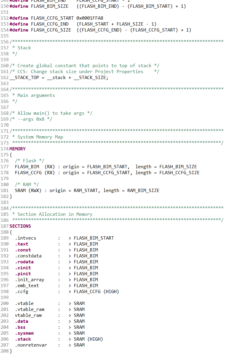
To extend the flash size of the BIM OAD, it is necessary to change linker script. But doing so will fail to boot because the vector table will move forward to the new BIM starting page. This is why is it necessary to manually update the following definition:
#define SET_CCFG_IMAGE_VALID_CONF_IMAGE_VALID 0x1F000
This will tell the ROM bootloader what the the BIM starting address is, which is also where the bootloader program Vector Table is.
CC2640R2F doesn’t start without JTAG Debug Probe
This problem can be a direct consequence of the previous points. If CC2640R2F doesn’t start without JTAG Debug Probe it could be due to the reset address stored in CCFG being wrong.
When loading a firmware in debug mode, the debugger will overwrite the default loading sequence and start directly at the image Startup address. So it will effectively start with JTAG.
#define SET_CCFG_IMAGE_VALID_CONF_IMAGE_VALID 0x1F000
Make sure this is the address of the bootloader start page.
—
Sources: TI e2e forum + own experimentation and analyses.