Category: Electronics

  • Bridging the Gap: Connecting Huawei ESM Batteries to Deye Inverters with ESP32

    Scaling to Remote Sites: Solving the Local Server Problem

    One common limitation with DIY energy monitoring is the assumption that the hardware and the Home Assistant (HA) server live on the same local network. But what about rental properties? To solve this, I designed the bridge to work over a Remote MQTT Architecture. By leveraging MQTT’s “Hub and Spoke” model, the bridge can be deployed anywhere with a simple Wi-Fi connection, while the management server remains at a central location.

    1. Firewall-Friendly Outbound Connections

    Instead of requiring complex VPNs or port forwarding at the remote site (which is often impossible on LTE/5G CGNAT gateways), the ESP32 initiates an outbound connection to a central broker. In the init_mqtt() function, we simply point the client to a cloud-hosted URL:
    mqtt_cfg.broker.address.uri = "mqtts://central.my-domain.com:8883"; mqtt_cfg.broker.verification.crt_bundle_attach = esp_crt_bundle_attach;

    2. Security via TLS Encryption

    Sending battery data over the open internet is a security risk. To mitigate this, I utilized the ESP-IDF CRT Bundle. This allows the ESP32 to verify the server’s SSL certificate using the same root CA logic as a modern web browser, ensuring the telemetry is encrypted and the source is authenticated.

    3. “Zero-Touch” Remote Maintenance (OTA)

    Deploying at a remote site means you can’t just plug in a USB cable to fix a bug. I implemented a remote Over-The-Air (OTA) update trigger via MQTT. By publishing a signed firmware URL to a specific command topic, the bridge can update itself anywhere in the world:
    if (strncmp(event->topic, "BMS/command/ota", event->topic_len) == 0) { // URL received via MQTT, trigger update task xTaskCreate(ota_task, "ota_mqtt_task", 8192, (void*)ota_url, 5, NULL); }

    4. Global Discovery

    Because Home Assistant’s MQTT Discovery is topic-based rather than IP-based, the remote bridge “appears” in the HA dashboard as soon as it connects to the central broker. This creates a seamless experience where data from multiple remote sites can be aggregated into a single, unified energy dashboard. This architecture transforms the project from a simple local converter into a professional-grade, scalable monitoring solution for distributed energy assets.

    Future Work

    The project is currently stable and running in a production environment.  Check out the source code and documentation on my GitHub.
    Keywords: ESP32, Huawei ESM48100, Deye Inverter, Solarman V5, Modbus RTU, Pylontech Emulation, Home Assistant, Energy Management.
      • Modbus Master: Polls multiple Huawei ESM packs for voltage, current, temperature, and cell-level data.
      • Protocol Emulator: Acts as a Pylontech BMS slave to the inverter, “tricking” it into seeing a compatible battery bank.
      • IoT Gateway: Monitors the inverter itself via the Solarman V5 TCP protocol and pushes data to Home Assistant.

    Technical Deep Dive: Solarman V5 Protocol

    One of the more interesting aspects was implementing the Solarman V5 protocol over TCP. Unlike standard Modbus TCP, Solarman wraps Modbus frames in a proprietary header (starting with 0xA5) and uses a custom checksum. 

    Home Assistant Integration

    To make the system user-friendly, I implemented MQTT Auto-Discovery. The bridge registers itself with Home Assistant the moment it connects to the network, creating sensors for everything from “Grid Power” to “Battery Cell Temperature” without any manual YAML configuration. This allows for beautiful dashboards and automation—like notifying me if a specific battery cell shows a voltage imbalance, or automatically adjusting load based on real-time solar production retrieved directly from the inverter’s logger.

    Scaling to Remote Sites: Solving the Local Server Problem

    One common limitation with DIY energy monitoring is the assumption that the hardware and the Home Assistant (HA) server live on the same local network. But what about rental properties? To solve this, I designed the bridge to work over a Remote MQTT Architecture. By leveraging MQTT’s “Hub and Spoke” model, the bridge can be deployed anywhere with a simple Wi-Fi connection, while the management server remains at a central location.

    1. Firewall-Friendly Outbound Connections

    Instead of requiring complex VPNs or port forwarding at the remote site (which is often impossible on LTE/5G CGNAT gateways), the ESP32 initiates an outbound connection to a central broker. In the init_mqtt() function, we simply point the client to a cloud-hosted URL:
    mqtt_cfg.broker.address.uri = "mqtts://central.my-domain.com:8883"; mqtt_cfg.broker.verification.crt_bundle_attach = esp_crt_bundle_attach;

    2. Security via TLS Encryption

    Sending battery data over the open internet is a security risk. To mitigate this, I utilized the ESP-IDF CRT Bundle. This allows the ESP32 to verify the server’s SSL certificate using the same root CA logic as a modern web browser, ensuring the telemetry is encrypted and the source is authenticated.

    3. “Zero-Touch” Remote Maintenance (OTA)

    Deploying at a remote site means you can’t just plug in a USB cable to fix a bug. I implemented a remote Over-The-Air (OTA) update trigger via MQTT. By publishing a signed firmware URL to a specific command topic, the bridge can update itself anywhere in the world:
    if (strncmp(event->topic, "BMS/command/ota", event->topic_len) == 0) { // URL received via MQTT, trigger update task xTaskCreate(ota_task, "ota_mqtt_task", 8192, (void*)ota_url, 5, NULL); }

    4. Global Discovery

    Because Home Assistant’s MQTT Discovery is topic-based rather than IP-based, the remote bridge “appears” in the HA dashboard as soon as it connects to the central broker. This creates a seamless experience where data from multiple remote sites can be aggregated into a single, unified energy dashboard. This architecture transforms the project from a simple local converter into a professional-grade, scalable monitoring solution for distributed energy assets.

    Future Work

    The project is currently stable and running in a production environment.  Check out the source code and documentation on my GitHub.
    Keywords: ESP32, Huawei ESM48100, Deye Inverter, Solarman V5, Modbus RTU, Pylontech Emulation, Home Assistant, Energy Management. In the world of residential solar and energy storage, mixing and matching components often leads to a common headache: communication protocol mismatch. Recently, I tackled a project to bridge the gap between high-capacity industrial Huawei ESM-48100 battery packs and a Deye Hybrid Inverter. The result is an ESP32-powered “BMS Bridge” that not only translates battery telemetry but also integrates deeply with Home Assistant via MQTT.
    The bridge acts as a multi-protocol translator in real-time.

    The Challenge: Industrial vs. Residential

    Huawei ESM series batteries are robust, industrial-grade units, but they speak a specific flavor of Modbus RTU. On the other side, residential inverters like Deye or Sunsynk typically expect a Pylontech-compatible CAN or RS485 protocol to manage charging parameters (SOC, Voltage limits, etc.). Without a bridge, the inverter is “blind” to the battery’s state, leading to inefficient charging and safety risks.

    The Solution: An Intelligent Protocol Bridge

    Using the ESP32 and the ESP-IDF framework, I developed a firmware that performs three simultaneous roles:
      • Modbus Master: Polls multiple Huawei ESM packs for voltage, current, temperature, and cell-level data.
      • Protocol Emulator: Acts as a Pylontech BMS slave to the inverter, “tricking” it into seeing a compatible battery bank.
      • IoT Gateway: Monitors the inverter itself via the Solarman V5 TCP protocol and pushes data to Home Assistant.

    Technical Deep Dive: Solarman V5 Protocol

    One of the more interesting aspects was implementing the Solarman V5 protocol over TCP. Unlike standard Modbus TCP, Solarman wraps Modbus frames in a proprietary header (starting with 0xA5) and uses a custom checksum. 

    Home Assistant Integration

    To make the system user-friendly, I implemented MQTT Auto-Discovery. The bridge registers itself with Home Assistant the moment it connects to the network, creating sensors for everything from “Grid Power” to “Battery Cell Temperature” without any manual YAML configuration. This allows for beautiful dashboards and automation—like notifying me if a specific battery cell shows a voltage imbalance, or automatically adjusting load based on real-time solar production retrieved directly from the inverter’s logger.

    Scaling to Remote Sites: Solving the Local Server Problem

    One common limitation with DIY energy monitoring is the assumption that the hardware and the Home Assistant (HA) server live on the same local network. But what about rental properties? To solve this, I designed the bridge to work over a Remote MQTT Architecture. By leveraging MQTT’s “Hub and Spoke” model, the bridge can be deployed anywhere with a simple Wi-Fi connection, while the management server remains at a central location.

    1. Firewall-Friendly Outbound Connections

    Instead of requiring complex VPNs or port forwarding at the remote site (which is often impossible on LTE/5G CGNAT gateways), the ESP32 initiates an outbound connection to a central broker. In the init_mqtt() function, we simply point the client to a cloud-hosted URL:
    mqtt_cfg.broker.address.uri = "mqtts://central.my-domain.com:8883"; mqtt_cfg.broker.verification.crt_bundle_attach = esp_crt_bundle_attach;

    2. Security via TLS Encryption

    Sending battery data over the open internet is a security risk. To mitigate this, I utilized the ESP-IDF CRT Bundle. This allows the ESP32 to verify the server’s SSL certificate using the same root CA logic as a modern web browser, ensuring the telemetry is encrypted and the source is authenticated.

    3. “Zero-Touch” Remote Maintenance (OTA)

    Deploying at a remote site means you can’t just plug in a USB cable to fix a bug. I implemented a remote Over-The-Air (OTA) update trigger via MQTT. By publishing a signed firmware URL to a specific command topic, the bridge can update itself anywhere in the world:
    if (strncmp(event->topic, "BMS/command/ota", event->topic_len) == 0) { // URL received via MQTT, trigger update task xTaskCreate(ota_task, "ota_mqtt_task", 8192, (void*)ota_url, 5, NULL); }

    4. Global Discovery

    Because Home Assistant’s MQTT Discovery is topic-based rather than IP-based, the remote bridge “appears” in the HA dashboard as soon as it connects to the central broker. This creates a seamless experience where data from multiple remote sites can be aggregated into a single, unified energy dashboard. This architecture transforms the project from a simple local converter into a professional-grade, scalable monitoring solution for distributed energy assets.

    Future Work

    The project is currently stable and running in a production environment.  Check out the source code and documentation on my GitHub.
    Keywords: ESP32, Huawei ESM48100, Deye Inverter, Solarman V5, Modbus RTU, Pylontech Emulation, Home Assistant, Energy Management.
  • Building a Real-Time AI Wildlife Monitor with ESP32-CAM and TensorFlow

    Developing a real-time wildlife monitoring system is a challenging yet rewarding project that combines hardware, machine learning, and web development. My latest project, WildLife Monitor, is an end-to-end solution designed to monitor safety conditions using an ESP32-CAM and a custom-trained Convolutional Neural Network (CNN).

    The Vision

    The goal was to create a system that doesn’t just “watch” but “understands.” Whether it’s monitoring a backyard for curious pets or ensuring an area is clear of hazards (like snakes), the WildLife Monitor provides real-time visual feedback and automated alerts based on what it sees.

    The Tech Stack

    • Hardware: ESP32-CAM (for low-cost, Wi-Fi-enabled video streaming).
    • Backend: Flask (Python) to manage the stream, data, and dashboard.
    • Computer Vision: OpenCV for frame processing and TensorFlow/Keras for the CNN model.
    • Messaging: MQTT for real-time safety alerts.
    • Frontend: A responsive web dashboard for monitoring and active learning.

    Key Features

    1. Real-Time AI Inference

    The system captures an MJPEG stream from the ESP32-CAM. Each frame is preprocessed and passed through a CNN model (model_cnn.h5). The dashboard overlays real-time predictions—identifying if a subject is present and whether the situation is “Safe” or “Unsafe.”

    2. Active Learning Pipeline

    One of the most powerful features of this project is the Active Learning workflow. When the model encounters a frame it isn’t confident about, or when I manually flag a frame, it’s saved into a review folder.

    • Manual Labeling: I built a dedicated interface to quickly categorize these “unknown” frames.
    • One-Click Retraining: Once labeled, I can trigger a model retraining session directly from the dashboard. This creates a feedback loop that constantly improves the model’s accuracy.

    3. Real-Time Alerting with MQTT

    Safety is the priority. When the system detects an “Unsafe” condition, it immediately publishes a message to an MQTT broker. This can be used to trigger physical alarms or send phone notifications.


    The Code Behind the Magic

    The backend handles the stream and runs inference in real-time. Here is a look at how the frames are processed:

    
    if model:
        try:
            input_data = preprocess(frame)
            preds = model(input_data, training=False).numpy()
            idx = np.argmax(preds[0])
            conf = np.max(preds[0])
    
            if idx < len(TRAIN_CLASSES):
                label = TRAIN_CLASSES[idx]
                color = (0, 255, 0) if "safe" in label else (0, 0, 255)
                cv2.putText(frame, f"{label} ({conf:.2f})", (10, 30), 
                            cv2.FONT_HERSHEY_SIMPLEX, 1, color, 2)
        except Exception as e:
            print(f"Inference error: {e}")
    

    What’s Next?

    Building this project highlighted the importance of data quality over quantity. In the future, I plan to:

    • Optimize for Edge: Move some of the inference directly onto the ESP32 to reduce latency.
    • Async Processing: Implement background threading for inference to maintain a high-FPS video feed.

    Conclusion

    WildLife Monitor is more than just a camera; it’s a smart assistant that learns from its environment. It bridges the gap between simple video surveillance and intelligent, reactive monitoring.

  • Building a Snake Deterrent with ESPHome

    Snakes are highly sensitive to ground vibrations, interpreting them as signs of nearby predators or large animals. This natural behavior can be leveraged to create a humane deterrent system: instead of relying on chemicals or barriers alone, we can generate irregular seismic signals that encourage snakes to move away.

    This project explores how to build a low‑cost, programmable vibration driver using an ESP8266 microcontroller and ESPHome firmware. By switching a 12 V hammer actuator in randomized bursts, the system produces unpredictable vibration patterns that mimic footsteps or animal movement. The result is a practical demonstration of how embedded systems, simple electronics, and open‑source firmware can be combined into a real‑world solution.

    Why Random Bursts?

    A steady metronome‑like vibration quickly becomes background noise. Random clusters of strikes, separated by unpredictable pauses, feel more “alive” and unsettling. This project uses ESPHome on an ESP‑01S relay board to generate those bursts automatically.

    Why 12 V Matters

    One important design choice was to keep the system at 12 V DC. Many garden devices unfortunately operate directly from 230 V mains, which introduces unnecessary electrical hazards in outdoor environments. By standardizing on 12 V, the system remains low‑voltage and touch‑safe, significantly reducing the risk of shock during installation, maintenance, or accidental contact.

    Hardware Setup

    • ESP‑01S WiFi relay board with external voltage regulator 12V -> 5V.
    • 12 V Selenoid Lock, used as hammer actuator mounted to a metal stick pushed into the ground
    • Shared 12 V supply: powers both the hammer and the relay board

    The relay switches the hammer coil, while ESPHome firmware handles the random timing.

    ESPHome Configuration

    Here’s the YAML configuration that runs the random burst script at boot, with a manual switch to enable/disable it:

    yaml
    esphome:
      name: esphome-relay2
      friendly_name: esphome relay2 snake hammer
      on_boot:
        priority: -10
        then:
          - if:
              condition:
                switch.is_on: random_enabled
              then:
                - script.execute: random_burst
    
    esp8266:
      board: esp01_1m
    
    switch:
      - platform: gpio
        pin: GPIO0
        name: "Relay2"
        inverted: true
        id: relay2
    
      - platform: template
        name: "Random Burst Enabled"
        id: random_enabled
        optimistic: true
        restore_state: true
        turn_on_action:
          - script.execute: random_burst
        turn_off_action:
          - script.stop: random_burst
    
    script:
      - id: random_burst
        mode: restart
        then:
          - while:
              condition:
                switch.is_on: random_enabled
              then:
                - lambda: |-
                    int burst = random(2, 5); // 2–4 strikes
                    for (int i = 0; i < burst; i++) {
                      id(relay2).turn_on();
                      delay(200); // hammer ON
                      id(relay2).turn_off();
                      delay(random(300, 1000)); // random pause
                    }
                - delay: !lambda "return random(5000, 15000);" // random gap before next burst
    

    How It Works

    • Burst clusters: 2–4 relay activations per cycle
    • Random intra‑burst delay: 300–1000 ms between strikes
    • Random inter‑burst gap: 5–15 s before the next cluster
    • Control switch: Exposed in Home Assistant and the ESPHome web UI, so the system can be disabled remotely

    Results

    The hammer delivers irregular seismic signals through the ground near entry points. Combined with perimeter lighting and physical barriers, this creates a layered deterrent system. It’s not a silver bullet, but it reduces surprise encounters and adds peace of mind.

    Final Thoughts

    This vibration deterrent system is no longer just a concept on paper — it is currently undergoing real‑world testing. The ESPHome‑driven relay board and hammer actuator are deployed and running continuous randomized bursts, allowing me to observe how the design performs outside of the lab. Early results are promising, but the ongoing field trials will provide the most valuable insights: durability of the hardware, consistency of the randomization, and, most importantly, the behavioral response of snakes to irregular seismic signals.

    By documenting this project as it evolves, I aim to demonstrate not only the technical implementation but also the practical effectiveness of combining embedded systems with behavioral cues in a real environment. This piece highlights the journey from idea to deployment — and the testing phase is where theory meets reality.

  • Reading a Huawei Battery BMS with an ESP32 and ESPHome

    A deep dive into reverse-engineering RS485 Modbus communication to bring industrial battery telemetry into Home Assistant.


    Background

    The Huawei ESM-48100 is a 48V 100Ah LiFePO4 energy storage module originally designed for telecom sites. It’s a well-built, high-density battery — but like most industrial hardware, it was never meant to talk to a home automation system. It exposes data over a 4-wire RS485 interface using Modbus RTU, and Huawei’s official protocol documentation sits behind an enterprise support portal.

    This project was about bridging that gap: taking a piece of industrial-grade battery hardware and making its internal data — state of charge, cell voltages, temperature, alarms — visible in Home Assistant through a $5 ESP32 and a $1 MAX485 transceiver.


    The Hardware Stack

    The physical layer is straightforward but required careful attention to the details.

    Components used:

    • ESP32-WROOM development board
    • MAX485 RS485 transceiver module
    • RJ45 cable terminated to the ESM-48100’s COM port

    The ESM-48100’s COM port is a standard RJ45 connector carrying 4-wire RS485 on pins 1, 2, 4, and 5, alongside CAN bus signals on pins 7 and 8. Only the RS485 lines were used for this project.

    Wiring the MAX485 Module

    The MAX485 chip has two sides — one facing the microcontroller, one facing the RS485 bus. A naming confusion that trips up many people: the module’s pins are labeled DI (Driver Input) and RO (Receiver Output), which reflect the chip’s own perspective, not the ESP32’s. DI connects to the ESP32’s TX line, and RO connects to the ESP32’s RX line.

    Some MAX485 modules expose separate DE and RE pins for flow control — these need to be tied together and driven by a GPIO on the ESP32. Others tie them internally, handling flow switching automatically. Both variants work at 9600 baud with Modbus RTU, though the manual DE/RE approach is more deterministic at higher speeds.

    A 120Ω termination resistor was placed across the A and B lines at the far end of the RS485 bus, as required by the Modbus standard to prevent signal reflections.

    Wiring Summary

    ESP32 GPIO16 (TX) → MAX485 DI
    ESP32 GPIO17 (RX) ← MAX485 RO
    ESP32 GPIO4       → MAX485 DE + RE (if exposed)
    3.3V              → MAX485 VCC
    GND               → MAX485 GND
    MAX485 A+  →  ESM-48100 RJ45 Pin 1 (RS485 T+)
    MAX485 B-  →  ESM-48100 RJ45 Pin 2 (RS485 T-)
    

    The Software: ESPHome and Modbus RTU

    ESPHome is a firmware framework for ESP32/ESP8266 that lets you define hardware integrations entirely in YAML. It natively supports Modbus RTU via its modbus_controller component, which handles framing, CRC, request queuing, and register parsing — so there’s no need to implement the protocol manually.

    The configuration defines:

    • UART component on GPIO16/GPIO17 at 9600 baud, 8N1
    • Modbus component that references the UART
    • Modbus Controller targeting slave address 0x01 with a 10-second poll interval
    • Individual sensors mapped to each holding register

    Register Map

    Sensor Register Scale
    Battery Voltage 0x0000 0.01 V/bit
    Battery Current 0x0001 0.01 A/bit (signed)
    State of Charge 0x0002 0.1 %/bit
    State of Health 0x0003 0.1 %/bit
    Remaining Capacity 0x0004 0.1 Ah/bit
    Max Cell Voltage 0x0005 1 mV/bit
    Min Cell Voltage 0x0006 1 mV/bit
    Max Cell Temp 0x0007 0.1 °C/bit
    Min Cell Temp 0x0008 0.1 °C/bit
    Average Cell Temp 0x0009 0.1 °C/bit
    Status Flags 0x000A bitmask
    Alarm Flags 0x000B bitmask
    Cycle Count 0x000C 1 cycle/bit

    ESPHome Configuration (excerpt)

    uart:
      id: uart_modbus
      tx_pin: GPIO16
      rx_pin: GPIO17
      baud_rate: 9600
      stop_bits: 1
      data_bits: 8
      parity: NONE
      flow_control_pin: GPIO4
    
    modbus:
      id: modbus_esm
      uart_id: uart_modbus
      send_wait_time: 250ms
    
    modbus_controller:
      - id: esm_bms
        address: 0x01
        modbus_id: modbus_esm
        update_interval: 10s
    
    sensor:
      - platform: modbus_controller
        modbus_controller_id: esm_bms
        name: "Battery SOC"
        register_type: holding
        address: 0x0002
        unit_of_measurement: "%"
        device_class: battery
        value_type: U_WORD
        filters:
          - multiply: 0.1
    

    Derived Sensors

    Beyond the raw registers, template sensors were added to derive useful secondary values:

    • Battery Power — calculated as voltage × current (W)
    • Cell Voltage Delta — max minus min cell voltage (mV), a key indicator of cell imbalance
    • Battery State — text sensor decoding the status bitmask into Charging / Discharging / Idle
    • BMS Alarm Active — binary sensor that fires whenever any alarm bit is non-zero

    The Hard Part: Finding the Register Map

    This was the most significant challenge of the project. Huawei’s Modbus protocol document for the ESM-48100 series is not publicly accessible without an enterprise support account. Community documentation is sparse, and what exists is scattered across energy storage forums.

    The ESM-48100 is documented as complying with the YDN1363 protocol over RS485. The register layout used in this project was sourced from community reverse-engineering efforts, not from the official Huawei document — which means it carries some uncertainty. A key caveat discovered during research: some firmware revisions use a 0x1000 base offset for all registers. If sensors return zeros or errors, shifting every address up by 0x1000 is the first thing to try.

    This kind of ambiguity is common when working with industrial hardware in hobby contexts. The approach taken here was to be explicit about what is verified and what is inferred, rather than presenting unverified information as confirmed fact — a discipline that matters when the output is a real electrical system.


    What This Enables in Home Assistant

    Once running, the ESP32 joins the home network and appears in Home Assistant as a device with 15+ entities. From there, the data feeds into:

    • Energy dashboards tracking charge and discharge cycles over time
    • Automations that respond to low SOC, high cell temperature, or active alarms
    • Long-term statistics on SOH degradation and cycle count growth
    • Notifications when the BMS alarm register goes non-zero

    The cell voltage delta sensor is particularly useful — a widening gap between max and min cell voltages over time is an early indicator that cells are drifting apart, which typically precedes a significant SOH drop.


    Reflections

    This project sits at the intersection of embedded systems, industrial protocols, and home automation. The hardware side — RS485 wiring, termination, flow control — required understanding the physical layer of the Modbus standard. The software side required navigating ESPHome’s component model, register types, and value scaling. And the research side required distinguishing between what Huawei officially documents and what the community has inferred.

    The result is a reliable, OTA-updatable, WiFi-connected BMS monitor that costs under $10 in hardware and runs indefinitely without any cloud dependency.


    Built with ESPHome and Home Assistant on an ESP32 with a MAX485 RS485 transceiver.
    Hardware: Huawei ESM-48100B1 LiFePO4 48V 100Ah energy storage module.

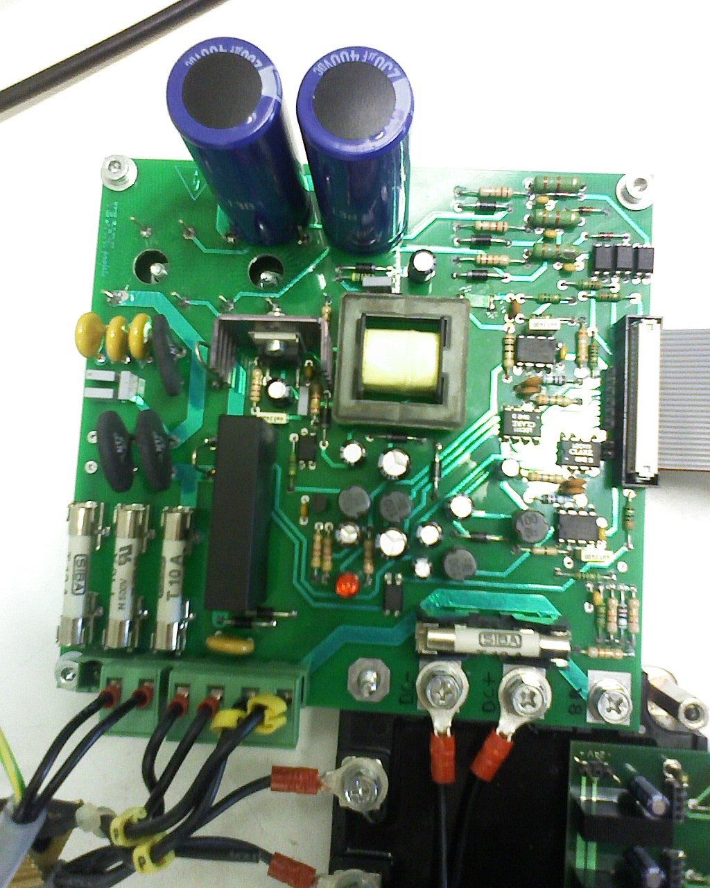
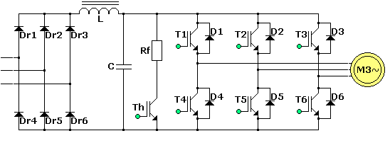
  • MCHP PIC p18f4431: Motor Control, 3-Ph, IGBT

    MCHP PIC p18f4431: Motor Control, 3-Ph, IGBT

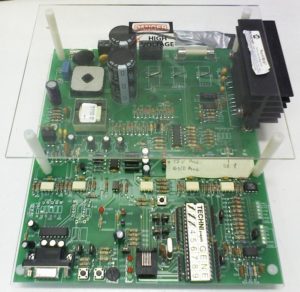
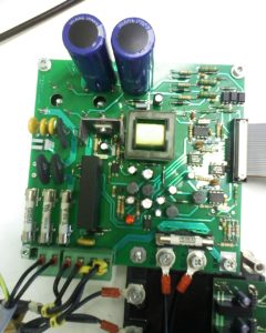
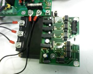
    Development of a 3-Phases motor speed control via PWM controlling IGBTs.
    + Technology watch and R&D.
    + Electronics Hardware (schematics, BOM, PCB layout including SMPS) .
    + Embedded software in bare metal C on Microchip PIC p18f4431.
    + 1KW 3-phases motor.
    + Current sensing.
    + H-bridge regenerative breaking.
    + Flyback DCDC power supply.
    (2006 – 2008)

  • The Popcorn Effect on MSL 1

    The Popcorn Effect on MSL 1

    A little break in Firmware development to help my client, an IoT start-up, diagnosing The Popcorn Effect. Something I’ve never seen with my own eyes before. The Popcorn Effect is a direct consequence of Moisture entering the IC before the reflow process. A common problem in Electronics Manufacturing.

    Production and Testing

    It all started on the assembly line, the IoT product is a kind of thermometer. The production has just started and the first pieces have arrived, ready for testing. One of the test consists of heating the thermometer up to 95°C, repeated 3 Times. It all worked fine up to 40°C when suddenly the software indicated 0°C for 9 of the devices. You would think they all worked fine until they reached that temperature. Some even recovered when cooling down.

    Inspection

    A first visual inspection of the PCBA by microscope doesn’t show any defect, all components are populated properly.

    Measuring the power supplies: it seems like it’s all fine.

    The sensor

    The temperature sensor is the TI TMP-100-Q1, connected to the host controller via I²C.

    Next step, how does the I²C CLK and DATA look like?

    They both look fine, except the data is always HIGH. So returning 0xFFFF to the app which represents -0.0625°C and then displays the nearest integer, 0°C.

    A closer look

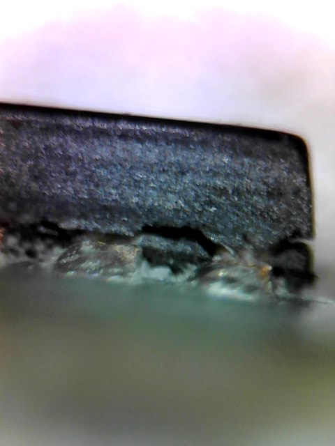
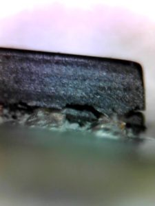
    A closer look with the microscope and yes, here we go. The IC is cracked at its base. Some chips present a slight crack between 2 pins, others show a very clear crack around the corner.

    The Popcorn Effect

    Because moisture found it’s way into the package and expanded in the reflow process, the IC pops like a popcorn.

    Manufacturers deliver the ICs in a sealed package if they are sensitive to moisture. MSL is the Moisture Sensitivity Level, provided by the manufacturer. This indicates how many hours an IC can be exposed to the ambient air before it needs to be baked to escape the trapped moisture in preparation of the reflow.

    The TI TMP-100-Q1 has an MSL 1, which generally means no particular precautions need to be taken. Despite this, level 1 does specify some limits. This example proves that from the chip production to the PCB reflow in Asia, moisture can affect the production even with a MSL 1 rated chip.

    Consequences

    In our case, most ICs stopped working, some only at higher temperatures, some recovered when cooling down. Imagine how many hours could be spend looking for a software bug on something as sporadic as that!

    Action

    The PCBA manufacturer has been notified of the issue and will cook all of these ICs before reflow. This is a standard process that consists of extracting moisture / drying the ICs for many hours at moderate temperature.

  • Cypress PRoC vs PSoC 4 BLE

    Cypress PRoC vs PSoC 4 BLE

    As for many new starters with Cypress Semi, I didn’t really know the major differences between PRoC and PSoC 4 BLE. In fact I didn’t even realise there was a difference. Yes there is. Luckily enough it is very simple!

    Cypress PRoC vs PSoC 4 BLE

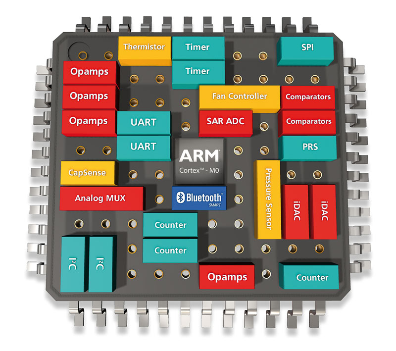
    Cypress PSoC 4 BLECypress’ PRoC (Programable Radio On Chip) can be seen as a subset of PSoC 4 BLE (Programable System On Chip). They have a similar core but PSoC offers a lot more analog blocks than PRoC. In fact PRoC provides only very basic analog blocks; There is no UDB, OpAmps nor Comparator. A simple comparison table can be seen on their Bluetooth Low Energy (BLE) Connectivity Solutions Overview. As an ex-Silicon Company Employee I would immediately think that the chips have actually the same DIE, but this is unlikely, because the ADCs are very different: SAR-ADC for PRoC vs Sigma Delta on PSoC 4 BLE.
    Why I use PRoC?

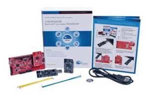
    CYPRESS SEMICONDUCTOR CY8CKIT-042-BLE DEV BOARD, PSOC 4 BLUETOOTH LOW ENERGY I started a development with PSoC 4 BLE and as it turned out the IoT device doesn’t need much analog part. In this case there’s a great price benefit to move to a PRoC module. These totally certified Bluetooth 4.x modules are some of the cheapest on the market in 2016 – 2017. What I really liked is that this ARM®-based chips have been around since 2015. This means it’s up and running, no Beta testing surprises. There’s also a community that can assist should you need it! I’ll go more deeply into my thought in a later post about my choice of Cypress and if this was a good plan or not.

    Thoughts for some hack

    It might be nice to point out that PRoC still has an SAR-ADC and a Capacitive Delta Sigma (CDS) block. The SAR-ADC has a 1Kohm equivalent serial resitor so might not be the best out there. However, could this CDS be hacked for fast analog acquisitions? I would think so, as long as you switch off all the auto-tune mechanism. It is essentially an excellent SNR ADC. To be explored!

  • Finding Electronic parts in Chiang Mai, Thailand 

    Finding Electronic parts in Chiang Mai, Thailand 

    Chiang Mai is a great place for Digital Nomad makers. There is one issue; If you are asking yourself “where can I buy electronic parts in Chiang Mai?”, this post might help you. Thailand is nothing like Shenzhen in China. So, where to find parts, raw components for makers and repairs?

    North Gate, Chiang Mai
    North Gate, Chiang Mai

    Through holes traditional electronics and breadboards

    The tiny shop near North Gate. Map.

    More traditional electronics, power supplies, boxes and kits

    The electronics shop on the North Road.

    North West corner, Chiang Mai
    North West corner, Chiang Mai

    Basic computer related things

    IT malls like Computer Plaza, North East corner.

    Adafruit and Arduino stuff

    Try your chance with Makerspace Thai. Situated in the old town, near Thae Phae Gate, this is a great place for makers.

    SMT and Anything else

    Non usual or SMT components: I’ve been cycling around a lot and there’s no miracle. You have to order online. There are sellers in Bangkok and it’ll take a few days but their websites are in Thai. Or buy on any usual online store. That’s what local professional do, they order on Aliexpress! And it’s cheaper too.

  • Choosing the right IoT Controller 

    Choosing the right IoT Controller 

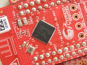
    detail of Cypress PSoC 4 BLE on CY8C4247LQI-BL483
    Cypress PSoC 4 BLE

    To choose the right controller for my IoT idea I start by listing the requirements. Some are essential others just nice to have. The controller is the brain of the system. All performances will depend on it so choosing the right device is essential. It is best to make this choice early to avoid a PCB redesign, rewritting the code, changing the specs.

    Essential requirements

    • Low sleep energy. Several weeks on battery, this implies different following choices.
    • Using Bluetooth Low Energy. This is a very common wireless connection present on most smartphones.
    • BLE certified module, worldwide, because the the low production volume would wouldn’t allow us paying for the certifications.
    • OTA firmware update. This could also be achieved with an external flash.
    • On chip user flash for parameter storage.
    • Capacitive touch sensor controller.
    • Lowest cost.
    • Several GPIOs for peripherals.
    • Easy starter kit to confirm my IoT idea is actually working before going any further.

    Nice to have

    • Battery level measurement.
    • On chip voltage regulator.
    • NFC, for easy pairing
    • For faster time-to-market, it is best to stay with a manufacturer or tools we already have experience with. In my case this was Atmel, Freescale, Microchip, Altera and more generally the ARM Cortex M0 and M4. Howewer, this project is part of my portfolio; I do not mind learning to use new tools and gaining new experience with an unknown manufacturer. In such case, there should be enough material and examples to get us started quickly.

    The candidates

    The following candidates were considered as they were available in July 2016. The market is evolving so there might be something more suitable now.

    • Cypress PRoC/PSoC 4 BLE. Flash 256k.
    • Nordic nRF52832. ADC 12bit 200ksps+ comparator wake up 0.3uA. Flash 256/512. Ram 32/64.
    • ATMEL SAM-B11.
    • Microchip MCP IS1871. BLE4.2.
    • Espressif ESP32.

    My IoT controller choice 

    I was looking for a module with integrated support for capacitive touch sensing. This was not available on Nordic, Atmel, Microchip and Espressif, leaving me with Cypress as only option. To keep a broader choice I looked into external touch sensor controller such as the Microchip CAP1203.

    Once you have selected the candidates it gets down to personal feelings. I’ve worked with the broad Microchip family, then went on Freescale for a few years. As an Ex-Atmel employee I know their products fairly well and some of them in very intimate details. Atmel has achieved the lowest current consumption on ARM. The development environment Atmel Studio is very mature, simple yet advanced using plugins. But this does not mean I’ll stick to something just because I know it well. Who knows me know that the reality is opposite; I like to explore, to discover, to learn, to setup new goals, new challenges.

    Cypress Cyble-012011-00
    Cypress Cyble-012011-00, a PRoC BLE module

    That’s how I choose the Cypress PSoC 4 for the following reasons :

    • Meets all the mandatory criteria.
      • Low sleep energy.
      • Bluetooth Low Energy.
      • BLE certified module available, royalty-free tested Bluetooth IP included.
      • On chip user flash.
      • Proximity sensor.
      • Enough GPIOs.
      • Starter kit CYBLE-CY8CKIT-BLE for quick feasibility check and development.
    • The Cypress PSoC 4 BLE is a very powerful device. I believe that acquiring experience with this ARM based controllers will open new opportunities.
    • Cypress has released the family over a year ago, which means it’s up and running. There’s ample material available, online video, 1o1 lessons, forums and customer service.

    I’ll write a separate post with my feedback with Cypress PSOC 4 BLE after a few months. Was this a good choice?

  • Visiting Seeed Studio in Shenzhen, China

    Visiting Seeed Studio in Shenzhen, China

    Seeed Studio LogoWhat is Seeed Studio?

    Seeed Studio is a company that specialized in providing help to makers to bring their hardware ideas to life.

    I am mainly looking for a manufacturer to produce IoT products. But before this, by sending them the design files they can already give me a price estimate for the product. So, we will know what the backer’s price should be for the crowdfunding campaign.

    Seeed Studio’s location

    I had a hard time finding Seeed Studio’s offices, mainly because Google maps is wrong. I used a VPN because it’s blocked but still. The pin is right on the satellite view but at the time of my visit, in Dec 2016, the map view was not aligned! If you can read Chinese just use Baidu Map. Otherwise see bellow.


    Here is the direction in English:

    Tower B 1/F, Shanshui Building, NanshanYungu Innovation Industry Park Liuxian Ave. No. 1183, Nanshan District Shenzhen ,Guangdong P.R.C 518055.


    And in Chinese, useful to ask any local or taxi:

    深圳市南山区留仙大道1183号南山云谷创新产业园山水楼1楼B

    Here are the directions to reach Seeed Studio by metro, it’s pretty easy once you know:

    • Get on Shenzhen’s metro line 5.
    • Get off at university town exit B.
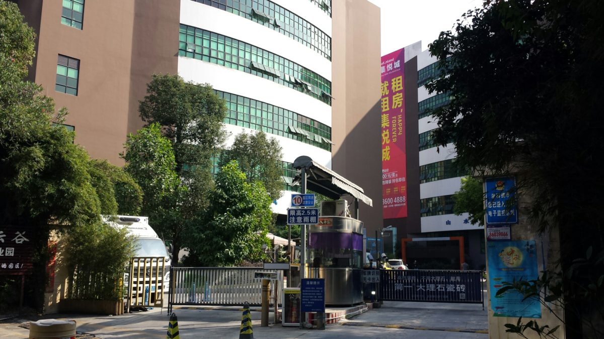
    • Walk straight until you reach this entrance:
    • Seeed Studio’s building IS NOT A TOWER! Pass on the left of the fountain and follow the building at your right, the entrance will be towards the end to your right.

    Seeed Studio’s services.

    Seeed is a hardware innovation platform for makers to grow inspirations into differentiating products. By working closely with technology providers of all scale, Seeed provides accessible technologies with quality, speed and supply chain knowledge. When prototypes are ready to iterate, Seeed helps productize 1 to 1,000 pcs using in-house engineering, supply chain management and agile manufacture forces. Seeed also team up with incubators, Chinese tech ecosystem, investors and distribution channels to portal Maker startups beyond.

    seeedstudio.com, Dec 2016.


    Of course I am concerned by sending them the design files. They are happy to sign an NDA but China is just so famous for copying everything, can we trust them? I don’t know but it seems like a lot of people have already trusted them.