Blog

  • [SOLVED] SRFPROG.exe sometimes stuck or crashed

    You might have experienced this same issue, presented on e2e.ti.com forum, but TI has “locked” my thread without answer. Here’s how to solve that for a very fast and reliable flashing usable in production.

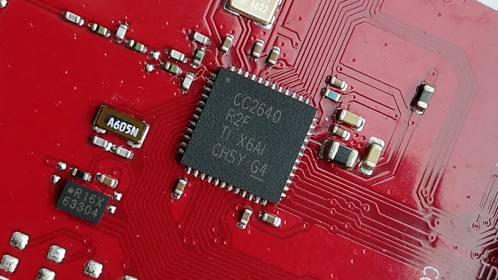
    We are trying to use srfprog.exe to flash the CC2640R2F, and it gets stuck very often, on any step or any argument, under Win-10 64, and using the JTAG from LaunchXL-CC2640R2. Note that SmartRF Flash Programmer 2 also gets stuck or crashes sometimes. I believe for the same reason.

    This, for example, is an output of srfprog where it got stuck and never returned:

    srfprog -ls auto
    
    Texas Instruments SmartRF Flash Programmer 2 v1.7.5-windows
    -------------------------------------------------------------------------------
    

    … stuck here.

    Here is the solution that has been proven to get srfprog.exe to work reliably without crashing for flashing TI’s CC2640 BLE chip family:

    • Wrap the srfprog calls into another program. Let’s call this wrapper srfwrap.
    • srfwrap will detect output activity from srfprog.exe .
    • If srfprog.exe is doing it’s job, it just goes on.
    • If srfprog.exe crashes or gets stuck, srfwrap will kill srfprog and restart the last command. Until it is successfully done.
    • Using this technique, I have been able to reliably program CC2640R2F in production.
    • Combined with other tools, programming the CC2640R2F can be as fast as under 40 seconds per chip, including the MAC address, a Serial Number, and securely locking the JTAG for unwanted access.

    I hope this helps, let me know in the comments 🙂

    Jerome

  • CC2640R2F: Secure bootloader for encrypted OTA update

    CC2640R2F: Secure bootloader for encrypted OTA update

    Development of a secure bootloader for encrypted OTA update via BLE.

    The bootloader has been developed in C in order to allow the OTA update of the Texas Instrument CC2640R2F, securely with an encrypted firmware image.

    The client controls the private keys and thanks to encryption techniques it is not possible to disassemble the firmware from it’s publicly shared binary.

    This secure bootloader is loaded on a genuine product and third parties cannot use the encrypted application image thus protecting the Intellectual Property from unwanted copies.

  • TI CC2640R2F: Start-up interrupt vector table explained

    TI CC2640R2F: Start-up interrupt vector table explained

    The TI CC2640R2F has a unique start-up sequence, based on the ARM core with TI’s ROM loader on top, here’s how it works!

    Prerequisite, General Facts

    • The BIM (bootloader) or application vector table is set by the linker to any known address.
    • The vector table holds the pointers to 15 ISRs out of 50.
    • On next hardware interrupt, the CPU jumps to the correct ISR using the vector table.
    • In OAD (over-the-air-download), the flash interrupt vectors of an image are located at the beginning of the image’s flash region right after the image’s header.  There are 15 interrupt vectors.
    • The CCFG contains the address of the user program Vector Table. In BIM the start address of the interrupt vector table is modified as follow:#define SET_CCFG_IMAGE_VALID_CONF_IMAGE_VALID 0x1F000Which is stored intoDEFAULT_CCFG_IMAGE_VALID_CONF @ CCFG_END – 5 * sizeof(uint32_t).

    How does the CPU know where the vector table is?

    Normally the Vector table must be located at a fixed absolute address (i.e. ‘reset’ address). However, Cortex-M3 allows to move the table using special register VTOR. In XDC this is

    “M3Hwi.vectorTableAddress = 0x20000000;”

    The XDC script initializes at compile-time a structure ‘Hwi_module’ with the new Vector Table address.
    The assignment is done in the function Hwi_initNVIC().

    “Hwi_nvic.VTOR = (UInt32)Hwi_module->vectorTableBase;”

    Hwi_initNVIC() is hidden and located in ROM at 0x1001a699.
    “\packages\ti\sysbios\family\arm\m3\Hwi.c”

    Where is the vector table on Reset?

    On reset, the vector table location register VTOR points to the ROM, @ 0x10000000 ! TBC

    The CC2640R2F has a ROM that contains a basic loader. There is more but that won’t be covered here.

    Boot procedure flow of operations

    1. ARM CPU reset, the vector table location register VTOR is pointing to ROM @ 0x10000000 ! TBC
    2. ARM CPU jumps to the ROM entry, the address is in the Vector Table.
    3. ROM loader copies the user program Vector Table to RAM @ 0x20000000. The address of the user program Vector Table is stored in the CCFG.
    4. The new Vector Table is in RAM at address 0x20000000 but VTOR has not yet been updated.
    5. ROM modifies the vector table location register VTOR to point to RAM @ 0x20000000.
    6. ROM reads the ResetISR from the RAM Vector Table and jumps to it.
    7. FLASH user program starts at ResetISR.
    8. FLASH user program running.

    with BIM OAD

    1. The first FLASH user program to start at ResetISR in the step 7 is the bootloader (BIM).
    2. BIM knows where or how to find an application Vector Table.
    3. BIM decides if the application is valid and if so will continue
    4. BIM jumps to the Application ResetISR.
    5. Application Starts.
    6. The current Vector Table is in RAM and still contains the BIM vector table copied in step 3.
    7. Application’s startup will copy its 15 own Interrupt Vectors from Flash into RAM and overwrite the vectors table.
    8. To specify the RAM address to copy the vectors to, this is done “indirectly” via the XDC script.
      “M3Hwi.vectorTableAddress = 0x20000000;”
    9. After this point, all interrupts and exceptions should be handled by the Application.
    10. Application Running.
    11. A reset will start this process again from the very first step.

    How to Debug Step Through with OAD BIM bootloader

    For development, it is always preferred to have a firmware as close as the release but with the capability of debugging it, stepping through it etc. There are several possibilities for achieving this:

    1. Stock bootloader

    The debug application firmware can have an empty header, that is not filled in. The application firmware is loaded in it’s memory space without overwriting the bootloader. The program pointer is altered via JTAG to point directly to the application entry point, effectively bypassing the bootlader. The CCFG is not overwritten.

    If an external system occurs, the bootloader will see the debug application firmware as invalid because its header is blank. As a result it will perform the necessary action for “missing” firmware. With Off-chip OAD this corresponds to flashing the latest image present on the off -chip flash memory.

    2. Debug Bootloader with NO_COPY

    To avoid the bootloader to reject the debug application firmware after a reset, it is possible to compile a modified bootloader with the definition NO_COPY enabled. This bootloader is skipping all check and jumping to the application firmware immediately.

    3. No bootloader

    For development purposes where the bootloader is not needed, best is to totally remove it.

    Make a new target without booloader, allocating that flash space for the Application Firmware. This extra flash space is helpful to be used for debug purposes, like extra debug functions, extra print string messages, or lower code space optimisation.

    The CCFG needs to be part of the application in order to contain the correct address of the user program Vector Table.

    BIM OAD extend size to more than one page

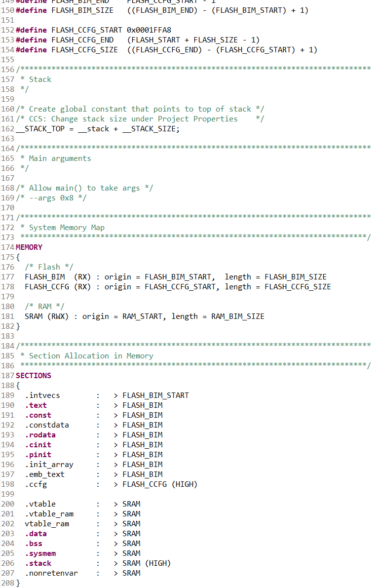
    To extend the flash size of the BIM OAD, it is necessary to change linker script. But doing so will fail to boot because the vector table will move forward to the new BIM starting page. This is why is it necessary to manually update the following definition:

    #define SET_CCFG_IMAGE_VALID_CONF_IMAGE_VALID 0x1F000

    This will tell the ROM bootloader what the the BIM starting address is, which is also where the bootloader program Vector Table is.

    CC2640R2F doesn’t start without JTAG Debug Probe

    This problem can be a direct consequence of the previous points. If CC2640R2F doesn’t start without JTAG Debug Probe it could be due to the reset address stored in CCFG being wrong.

    When loading a firmware in debug mode, the debugger will overwrite the default loading sequence and start directly at the image Startup address. So it will effectively start with JTAG.

    When using BIM OAD, after reset, the ROM loader will use the address provided in “ccfg_app_ble.c” and placed into CCFG:
    #define SET_CCFG_IMAGE_VALID_CONF_IMAGE_VALID 0x1F000
    Make sure this is the address of the bootloader start page.
    Sources: TI e2e forum + own experimentation and analyses.
  • MCHP PIC p18f4431: Motor Control, 3-Ph, IGBT

    MCHP PIC p18f4431: Motor Control, 3-Ph, IGBT

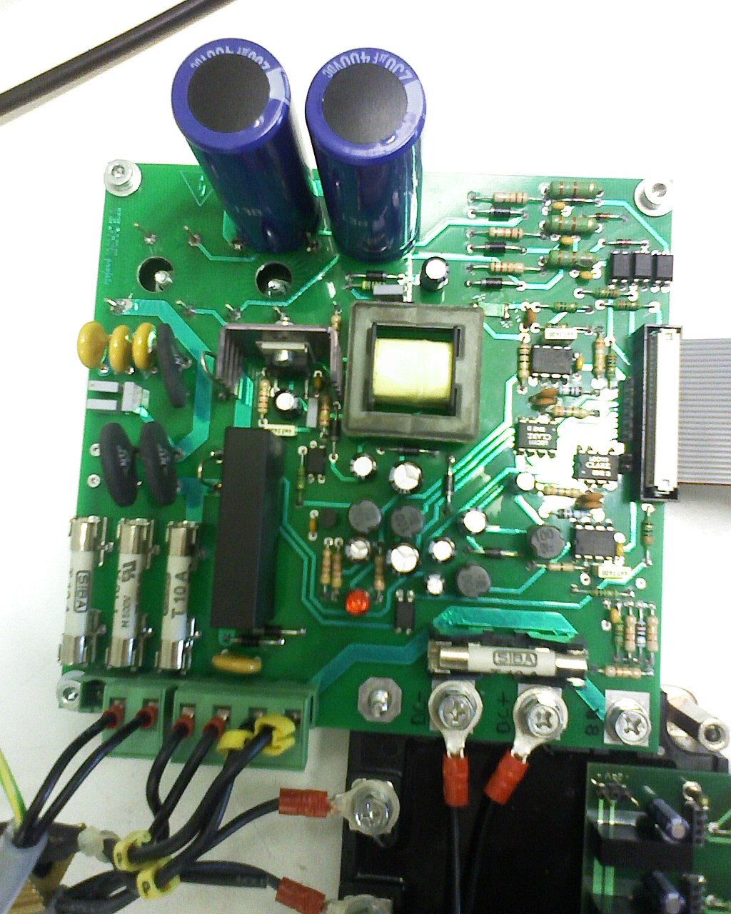
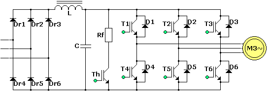
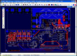
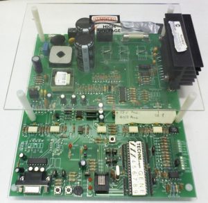
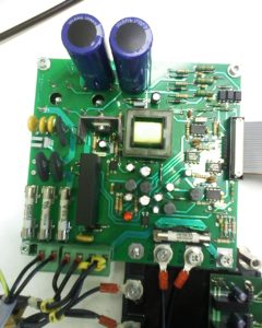
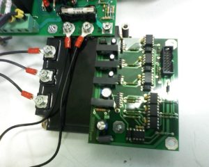
    Development of a 3-Phases motor speed control via PWM controlling IGBTs.
    + Technology watch and R&D.
    + Electronics Hardware (schematics, BOM, PCB layout including SMPS) .
    + Embedded software in bare metal C on Microchip PIC p18f4431.
    + 1KW 3-phases motor.
    + Current sensing.
    + H-bridge regenerative breaking.
    + Flyback DCDC power supply.
    (2006 – 2008)

  • CC2640R2F: Smart Bluetooth Low Energy BLE Central (client)

    CC2640R2F: Smart Bluetooth Low Energy BLE Central (client)

    Development of a BLE central; The device is setup as a client, it connects to one or multiple Bluetooth sensors at the same time and without time multiplexing. The central gathers the information, processes them and takes action accordingly. With the TI CC2640R2F it runs on a single AAA battery.
    [Project is still confidential, more details to come later]
  • Cypress PSoC Central for multiple peripherals

    Cypress PSoC Central for multiple peripherals

    Are you considering using Cypress’s PSoC 4 BLE to run as a central?

    Cypress offers a wide range of BLE 4.x System on Chip (PSoC) and Radio on Chip (PRoC) as well as plenty of certified modules for a faster time to market.

    They also offer various basic embedded software example codes, which are very important for a successful development.

    Many BLE systems are used as Peripherals, running a GATT Server. A client can connect to the peripheral and typically performs read / writes on its characteristics.

    One type of popular Client are smartphones, they are usually used for user setup, gathering data and general interaction with the Bluetooth peripheral.

    It is also possible for Cypress’s PSoC 4 BLE to act as a client. The IoT chip can scan for advertisement data, get the scan response, connect to the peripheral, discover its characteristics, and perform read/write/notify on them.

    Multiple peripherals

    Cypress’s PSoC 4 BLE does not support simultaneous connection to multiple peripherals.

    They however advertise what they are calling “time multiplexing”.

    What is Cypress’s PSoC connection time multiplexing? 

    Behind this marketing term “time multiplexing” is a very basic concept : because PSOC 4 BLE used as a central cannot connect to multiple peripheral at once, the central will connect to one peripheral after another, one at a time… as easy as it sounds.

    A typical application for a PSoC 4 BLE Time Multipled Central (TMC) could follow a sequence like this :

    1. Scan for all peripherals.
    2. Connect to the first peripheral and discover its characteristics.
    3. Disconnect.
    4. Connect to every other peripheral and discover their characteristics in a similar manner.
    5. Bond to all peripherals the system is interested with.
    6. Connect to one of the peripheral.
    7. Do the necessary Read/Write operations.
    8. Disconnect.
    9. Repeat operations #6 to #8 in a loop with every peripheral.


    Why is Cypress’s Time Multiplexing a bad approach? 

    While a BLE Time Multiplexed GAP Central seems easy and works fine, there’s a couple of reasons why this approach is very bad.

    Power (in)efficiency

    First, BLE stands for Bluetooth Low Energy, and as the name implies, it has been designed to be energy efficient. The time multiplexing does not allow to take profit of the design and thus is very inefficient.

    In BLE, the connection is maintained open by periodical short messages (Connection Interval), this is handled at the low level (Link Layer), allowing the application to sleep. Cypress’s solution for a multi peripheral central implies CPU and BLE overhead due to the connection /disconnection. This affects both central and the peripheral.

    Notification/Indication 

    BLE has a Notification/Indication system that can notify the client of a change in the peripheral’s value. Doing so there’s no need of constantly polling the data. Both central and peripheral can sleep as long as there’s no data update.

    These flags are disabled by default and it is required to activate them by performing a write operation to the CCCD (Client Characteristic Configuration Descriptor) of the corresponding characteristic.

    Most peripherals reset all flags on disconnection, thus making it useless with Cypress’s time multiplexing.

    Stolen peripheral 

    BLE is now widely used and everyone has a smartphone capable of connecting to any peripheral that is advertising. Once connected, the peripheral will stop advertising because it is already connected and cannot accept a new connection.

    This means that if you have 4 devices you connect to in a time multiplexed manner, each device will be available and connectable 3/4 of the time.

    During this time, should anyone connect to the device, it’ll be invisible to the central and impossible to connect to. Connecting to a peripheral could be intentional or unintentional. What I’ve learned from experience and very concerning in an industrial environment is that bugs in some Android devices lead Android not willing to disconnect from the peripheral even though the Bluetooth is switched off in the UI! The only reliable solution found is to reboot the Android phone.

    Placeholder for research : would BLE authentication improve this issue by avoiding a hacker to connect to the peripheral?

    Could the BLE component be improved 

    Cypress’s BLE component could certainly be improved in various manners, but the limiting RAM space and lack of low layer documentation seems to make this solution very difficult. I think this development time should be spent doing a better user application rather spending time on developing a proprietary BLE driver

    The advantages of BLE Time Multiplexed Connection

    The main advantage by far of such a system is to be able to connect to an unlimited number of peripherals. Whether there are 4 or 40 sensors in the system, there is not much difference from the central’s point of view. The connection time will of course be shared between all sensors with all the downside listed above.

    Most sensors are battery powered, it is possible for the user application to sleep while no client is connected and wake-up only once a connection request is received. Advertisement is handled by the link layer, no need for the user application to run.

    Other solutions 

    I have successfully developed a BLE central client, able to connect with multiple simultaneous peripherals at once. The central is maintaining connections for 4 peripherals while advertising and allowing connection of a client to its own GATT server. The low power client also supports all the benefits of BLE including Notifications and CPU sleep. However, the BLE central is based on a TI CC2640R2F instead of Cypress’s solution.

    Are you looking to create your own BLE central device, taking advantage of the low power design of the wireless connection? I am looking forward to discuss your needs, contact me now: jerome at yupana-engineering.com!


  • Hands on TI CC2640R2F

    Hands on TI CC2640R2F

    This is my first experience with CC2640R2F and also with TI more generally so I thought I’ll write down my feelings after a week as it might be of interest to someone else.

    Background

    I should mention that this was my very first time developing with TI, which means most of the comments concern TI more than the CC2640R2F specifically. I have been developing with other brands like Atmel, Microchip, Motorola and Cypress so there will be some kind of comparison with them.

    Goal and expectations

    I’ve been given a week to evaluate the CC2640R2F and try to estimate the required time for achieving the corresponding project. The accent is put on the capacity to connect up to 4 peripherals and one client. The connection needs to automatically be established and reconnected if disconnected.

    The chip

    The TI CC2640R2F is an improved version of the famous TI CC2640. The main difference is that the radio stack stays in an added ROM memory. This leaves more flash space for the user application. The chip is also ready for Bluetooth 5.0 once the Stack and SDK will be released. The main difference on this is a reduced link budget for an extended range, perfect for IoT.

    LAUNCHXL CC2640R2 LaunchPad demo board

    I have been using the Launchpad which contains the Smart Bluetooth CC2640R2F controller, a Serial over USB chip also used for ISP and debugging, 2 leds and 2 user buttons.

    Installation

    Installation was long, on my computer it took a few hours for

    • BLE SDK and
    • code composer studio 7 (CCS 7).

    I made the mistake of choosing my own install directory, this is strongly unadvertised so after some errors I reinstalled everything again. this was on my “old” laptop so it might be quicker for you.

    CCS7

    Code Composer Studio 7 is based on eclipse that I already know from Android Apps development. However, the default view doesn’t show all the features I am used to have but that’s just a matter of configuration.

    Hello World

    As a hello world project I choose the “simple central” example project because it is close to my needs. Later I found the “multi role” project that’s even closer.

    Firstly impossible to compile : missing xxx files. Surely they are not in the directory, but how to get them in? I searched the forum but couldn’t find the answer so I asked for it. One user was quite quick for replying. It turns out you have to import the project API too, called “project name api”. Unfortunately CCS7 does not give you any hint why the files might be missing.

    Help

    I anticipated the problem that comes with every new IDE and system and ask for help. Tutor XYZ* who’s a professional that’s been working closely with and for TI briefly introduced me to the chip family and helped me to start. It is so much more convenient with someone’s help 🙂

    I asked my tutor and several other people, where is the documentation for the “simple central” or “multi role” examples. Surely there is. To that I got only very generic answers, “there isn’t any”, there’s a wiki and there’s a forum just ask everything there.

    The good news is that there is documentation, the bad news, it’s all over the places. So let’s list them:

    – SimpleLink academy. Learn about Smart Bluetooth applied to TI’s stack.

    – TI SDK user guide. I first discarded this document because I don’t understand what examples are doing in the SDK user guide. Still, this is where you will find the most complete and valuable information.

    – c:/ti/sdk_xxx/ directory. Mainly a doxygen help but does also provide information.

    – The forum e2e. This chip family has been around for years, so there should be a lot of common questions already answered. Unfortunately the search tool is not so good.

    – GitHub. Yes, there’s quite a lot of codes and guides that can’t be found anywhere else. I avoided GitHub at first because CCS7 has a cloud based Explorer so the content should be the same. The code is probably but the doc is definitely present in GitHub and missing in CCS7. FAIL. The search results is the best because it is looking into projects from similar controllers too. This brings us to the last point.
    https://github.com/ti-simplelink/ble-sdk-210-extra/tree/master/Projects/ble/multi_role

    – CC2640. Of course most of the examples and documentation for the CC2640R2F is the same as for the CC2640, make sure your searches include both.

    *XYZ. I prefer not to disclose the person’s name until I get approval to do so.

    EDIT 21.03.2017: It seems like TI read in my mind (or got my feedback via XYZ?), they now provide a description for each example directly in CCS’s cloud! It’s however not at the root but you should find it at two parent level from it.

  • Cypress PRoC vs PSoC 4 BLE

    Cypress PRoC vs PSoC 4 BLE

    As for many new starters with Cypress Semi, I didn’t really know the major differences between PRoC and PSoC 4 BLE. In fact I didn’t even realise there was a difference. Yes there is. Luckily enough it is very simple!

    Cypress PRoC vs PSoC 4 BLE

    Cypress PSoC 4 BLECypress’ PRoC (Programable Radio On Chip) can be seen as a subset of PSoC 4 BLE (Programable System On Chip). They have a similar core but PSoC offers a lot more analog blocks than PRoC. In fact PRoC provides only very basic analog blocks; There is no UDB, OpAmps nor Comparator. A simple comparison table can be seen on their Bluetooth Low Energy (BLE) Connectivity Solutions Overview. As an ex-Silicon Company Employee I would immediately think that the chips have actually the same DIE, but this is unlikely, because the ADCs are very different: SAR-ADC for PRoC vs Sigma Delta on PSoC 4 BLE.

    Why I use PRoC?

    CYPRESS SEMICONDUCTOR CY8CKIT-042-BLE DEV BOARD, PSOC 4 BLUETOOTH LOW ENERGY I started a development with PSoC 4 BLE and as it turned out the IoT device doesn’t need much analog part. In this case there’s a great price benefit to move to a PRoC module. These totally certified Bluetooth 4.x modules are some of the cheapest on the market in 2016 – 2017. What I really liked is that this ARM®-based chips have been around since 2015. This means it’s up and running, no Beta testing surprises. There’s also a community that can assist should you need it! I’ll go more deeply into my thought in a later post about my choice of Cypress and if this was a good plan or not.

    Thoughts for some hack

    It might be nice to point out that PRoC still has an SAR-ADC and a Capacitive Delta Sigma (CDS) block. The SAR-ADC has a 1Kohm equivalent serial resitor so might not be the best out there. However, could this CDS be hacked for fast analog acquisitions? I would think so, as long as you switch off all the auto-tune mechanism. It is essentially an excellent SNR ADC. To be explored!

  • PCB layout with Target3001! 

    PCB layout with Target3001! 

    After validating the feasibility of my IoT idea, I wanted to start drawing the schematic. There are plenty of PCB layout CAD software. Target3001 was in the list.

    Target3001! logo

    Why Target3001?

    I did not own a licence and prices are high, you better choose the right tool. Fortunately most of them have a free trial, perfect for evaluation before buying. This is how I ended up discarding my first choice: Element14 Circuit Studio made by Altium was a FAIL.

    My second choice went to Target3001 made by IBF in Germany. I used to work a lot with this software at the start of my career. It is not really popular but it is a serious electronic schematic and layout CAD tool. I don’t recall using Kikad or any other open source version because I consider them to be too basic or not professional enough.

    This was back in 2010 and Target3001 already featured the famous 3D view. I remember it to be average and buggy but wanted to see if IBF did any improvement.

    How did it go?

    While the design software is not so beautiful, it is mature and implements a lot of advanced functions. I did experience a few bugs but nothing to worry about.

    Eventually, I ended up drawing the whole electronic schematic and started the layout. The weakest point was applying changes, pushing a track doesn’t automatically push its neighbors as it does in some other CAD tools. In fact, it doesn’t even keep the angles or anything. So if you move things around for any reason the resulting work is very heavy.

    Creating a component is easy once you understand the philosophy, where the coordinates are etc. If you decide to give Target3001 a try you will need to create a component; the default library is lacking of SMT components, but there shouldn’t be any problem concerning through holes.


    I was rather unhappy with the default silk screen of the provided library of SMT components, it is way too large. The solution was quite simple. I draw my own silk screen layer, smaller and thinner. I produced the red PCB with PCBGOGO and the result looked nice on the board.


    IoT PCB designed in Target3001!
    My PCB designed in Target3001!

    Would I recommend Target3001?

    I am not sure how easy it is to learn using Target3001 from scratch because I new it already. That said, if you want a cheaper and good electronic design software to design your IoT device, I suggest giving it a try and let me know your thoughts.

  • PCB design with Altium Circuit Studio. FAIL.

    PCB design with Altium Circuit Studio. FAIL.

    Altium Circuit Studio sold by Element14 (Farnell) is a stripped down and cheaper version of the famous Altium Designer.

    I thought I’ll give it a try as they just reduced the price to about 1000$. This makes it competitive with others in the same feature and price range.

    I installed the 30 days trial and started to design the schematic of my IoT project. I have used Altium Designer and even Protel during my studies so not so difficult to remember basic usage.

    I quickly noticed a lot of bugs, crashes and very bad user experience (UX). It finally went to a point that the whole software became unusable due to constant crashes.

    I reported a rather long list of issues that was left without answer. Until another user raised the same major issue on the Element14’s forum: the minimal screen resolution shall be at least 1280 x 1024. Following my complain they finally got in touch but the conclusion is pretty deceiving for Digital Nomads using an ultra portable:

    For any customers using lower res laptops, they get around this limitation by using sw that allows scrolling of the screen. I know it is not the answer the customer is looking for but we do appreciate the candid feedback.

    Altium via Farnell, 2016-11-04

    Altium also assured that the crashes are not common but they don’t have a solution. Trying Circuit Studio was a FAIL for me. I wish it would work as it looks nice and I recommend you to try it. I’ll certainly give it another try with a new computer. But for now it led me to go back towards IBF Target3001 which I used to work with when I started my career.